
Tube Inspection:
ATIC provides different tube inspection services utilizing our Advanced Tube Inspection System. This advanced tube inspection system has bundled four inspection technologies into a single unit. Internal Rotary Inspection System (IRIS), Eddy current, Remote Field Testing, and Magnetic Flux Leakage (MFL).
The ECT, RFT & MFL are high-speed, multichannel, multi-frequency scanning system with advanced reporting and tube sheet mapping software.
The IRIS system is a single channel ultrasonic scanning system with the ability to inspect tubes in a wide range of diameters with advanced reporting.
IRIS Inspection Technique:
Tube Inspection with IRIS for Ferrous and Nonferrous Materials Boilers Feed water heaters Air coolers Heat exchangers.
Characteristics of the IRIS technique:
- Suitable for ferrous and non-ferrous material.
- Detects general thinning such as corrosion and erosion and localized defects such as pitting and wear.
- Measures the absolute wall thickness value, as well as the internal and external diameter of the tube.
- Accommodate a wide range of tube diameter and wall thickness.
- Tube cleaning is VERY important to avoid loss of echoes.
- Typical pull speed of 50mm/s (2in/s).
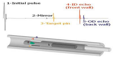
IRIS Working Principles:
A transducer located inside a turbine generates an ultrasound pulse along the axis of the tube.
The ultrasound is reflected on a 450 mirror and oriented toward the tube wall thickness.
The ultrasound is partially reflected on the ID, then transmitted inside the wall, and finally reflected on the OD. Knowing the ultrasound velocity in the tube material, the wall thickness can be calculated by using the time of flight difference between the OD and ID echoes A water flow is going inside the cable and then through the turbine The mirror, attached to the rotor part of the turbine, rotates continuously at a speed of about 50 rev/s. This rotation allow a full inspection of the tube wall thickness A small pin attached to the turbine body produces an ultrasound reflection each time the mirror passes under it. The reflection from the pin is used to synchronize the screen display.
IRIS Applications:
- Allows for the detection and sizing of wall loss as a result of corrosion, erosion, tube-to-tube wear, pitting and baffle cuts.
- Focused ultrasonic probe and a rotating mirror to produce a helical scan.
- Ultrasound is reflected from the tube ID and OD and the time difference is used to calculate the thickness.
- IRIS is a great backup and verification tool for the other tube inspection techniques.
- IRIS data to be presented as a B, C, or D-scan image.
ECT Inspection Technique:
Tube Inspection with Eddy Current:
Condensers, Feed water heaters, Heat exchangers & Air conditioners.
Characteristics of the ECT technique:
- Suitable for non-ferrous tubing such as SS304/316, Brass, Titanium, Cu, Cu-Ni, etc.
- Can detect pits, corrosion, erosion and axial cracking.
- Uses multiple frequencies for better analysis and flaw sizing.
- The probe needs a good fill factor to remain sensitive (about 0.85 to 0.9).
- Probe centering is important for uniform sensitivity and reduce lift-off signal.
- Very fast technique, up to 2m/s pulling speed.
ECT Working Principles:
- Alternating current injected into a coil creates a magnetic field.
- When this coil is placed over a conductive part, opposed alternating currents are generated, they are the eddy currents.
- Defects in the part disturb the path of eddy currents which can be measured by the coil.
- Two coils are excited with an AC current; producing a magnetic field around them.
- The magnetic field penetrates the tube material and generate opposite AC current in the material. Those currents are called "eddy currents".
- Any defects that change the eddy current flow circulation will change in impedance of the coils in the probe.
- Those changes in the impedance of the coils are measured and use to detect the defects in the tube.
RFT Inspection Technique:
Tube Inspection with Remote Field Testing:
Boilers, Feed water heaters, Air coolers & Carbon steel heat exchangers
Characteristics of the RFT technique:
- Suitable for ferromagnetic pipes and tubes such as those found in boilers and heat exchangers.
- Same sensitivity to internal and external flaws.
- Relatively insensitive to probe liftoff or wobble.
- Easily examines very thick tube wall (up to 12 mm).
- Small fill factor is required which enables the inspection of partially scaled tubes and boiler
- tubes with swages and bends.
- Centralization of the probe is not as critical as it is for ECT inspection.
- Typical pull speed between 0.15 and 0.3 m/s.
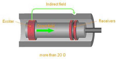
RFT Working Principles:
- The basic probe is made with one exciter and two receiver coils.
- Two primary paths exist for coupling the energy between the exciter and the receivers.
- The direct field is localized around the exciter and rapidly attenuated with distance down the pipe.
- The indirect field diffuses outward through the pipe wall, moves along the pipe, and re-diffuses back through the pipe wall.
- The zone in which this indirect field is dominant is called the remote field zone. This append at a distance higher than two pipe diameters.
MFL Inspection Technique:
Tube Inspection with Magnetic Flux Leakage:
Boilers, Feed water heaters, Air coolers & Carbon steel heat exchangers.
Characteristics of the MFL technique:
- Suitable for ferromagnetic tubes such as carbon steel, nickel, and ferritic stainless steel.
- Typically used for air cooler and heat exchanger tubes, the technique can detect pitting, circumferential cracks and wall losses.
- Defect sizing is limited because the signal amplitude is affected by the pulling speed variations, and also because there is no phase component on the signal.
- The fill factor is similar to the eddy current technique
- Tube cleaning is most of the time required (not as critical as it is for IRIS).
- The probe has to be centered to keep a uniform sensitivity to localized defects.
- Quick technique for which the pulling speed can go up to 1m/s. often used in combination with IRIS.
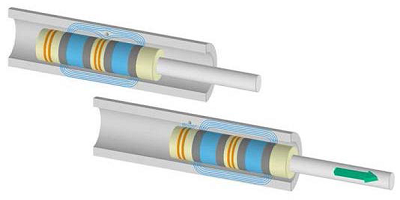
MFL Working Principles:
- Two strong permanent magnets, coupled with a steel core, generate a strong magnetic field that saturates the tube wall.
- An absolute coil is winded around the core to measure magnetic field variation caused by general wall losses.
- When a small flaw is located between the two magnets, the magnetic field in the tube wall is disturbed and a small amount of flux leak into the inner tube.
- This flux leakage is detected by a differential coil (Lead), located between the magnets.
- A trailing coil at the end of the probe detects the residual magnetism coming from internal pits.
- If an outside defect is located in the tube The saturation flux lines are deviated in the air but also inside the tube. Since the tube wall is already saturated, the flux line deviated cannot be contained in the remaining wall and flux leakage is created on the ID.
- If there is an inside defect, the saturation flux lines are deviated in the tube when the magnetic circuit passes under the defect.
- At this point, the LEAD coil can detect the flux leakage created.
- After the magnetic circuit passes the defect, some residual magnetism remains on the defect.
- The TRAIL coil will detect this residual magnetism and produce a signal output to the system.